

FAQ
What are the precautions when installing power supplies in the end system?
 The AC power line shall be turned off, and live wire connections shall not be exercised. Turn on AC power after all connections have been properly made to avoid the electrical hazard.
 The AC power line shall be turned off, and live wire connections shall not be exercised. Turn on AC power after all connections have been properly made to avoid the electrical hazard.
 Pay attention to the maximum length of mounting screws as specified in the datasheet. If the length exceeds the specifications, the screw may come in contact with internal components and cause electrical failures or even endangerment. Please refer to the installation manual for the appropriate torque settings and wire gauge.
 When the system is Class I installation, connect the power supply frame ground (FG) with the system frame ground (FG). For more details on installation precautions, please visit Selection Guide-Installation Manual and download the corresponding installation manuals per product types.
EMC debugging suggestions for end systems with integrated power supplies
MEAN WELL power supplies comply to EMC requirements by themselves, but since power supplies are components, the EMC performance of the end system my not be compliant and needs to be evaluated as a whole. When there are EMC related issues, you may try the suggestions below:
1. Add EMI filter to the power supply input
2. Add grounding choke
3. Add EMI cores to the AC or DC cables
What is class 2, class II and LPS? What is the difference between class I and class II?
Class I: Equipment where protection against electric shock is achieved by using basic insulation and also providing a means of connecting to the protective earth conductor in the building whereby routing those conductive parts that are otherwise capable of assuming hazardous voltages to earth ground if the basic insulation fails. This means a class I SPS will provide a terminal/pin for earth ground connection.
Class II: Equipment in which protection against electric shock does not rely on basic insulation only, but in which additional safety precautions, such as double insulation or reinforced insulation are provided, there is no reliance on either protective earth or installation conditions. This means a class II SPS does NOT have a terminal/pin for earth ground connection.
The decision on whether to use Class I or Class II power supplies is typically dictated by the end system. If the end system is Class I type, please select Class I power supply, and if the end system is Class II type, please select Class II power supply to avoid performance issues with EMI, hi-pot, etc.
Protection features of power supplies
When current drawn exceeds the rated output current of the power supply, the protection circuit will be triggered to protect the power supply against overload/overcurrent.
Protections of overload/overcurrent can be divided into several forms:
(1)FOLDBACK CURRENT LIMITING
Output current decreases about 20% of rated current, shown as curve (a) in the figure below.
(2)CONSTANT CURRENT LIMITING
Output current remains at a constant level and within the specified range while the output voltage drops to a lower level, shown as curve (b) in the figure below.
(3)OVER POWER LIMITING
Output power remains constant. As output load increases, the output voltage decreases in proportion, shown as curve (c) in the figure below.
(4)HICCUP CURRENT LIMITING
Output voltage and current keep pulsing ON and OFF repeatedly when protection is activated. The unit automatically recovers when faulty condition is removed.
(5)SHUT OFF
Output voltage and current are cut off when the output load reaches the protection range.
NOTE: Protection mode of some of the products combines with different types of forms mentioned, such as constant current limiting + shut down.

Recover method:
(1)Auto Recovery: PSU recovers automatically after fault condition is removed.
(2)Re-power on: PSU restarts by manual AC re-power on after fault condition is removed.
Note:Please do not operate PSU in overcurrent or short-circuit condition for a long period of time to prevent a shorten lifespan or damaging the PSU.
What should be taken into considerations when PSUs are in parallel connection?
When power supplies are connected in parallel, we can increase the output current or use them for the redundant (back-up) function. Be sure that the tolerance of output voltage and wiring impedance are very small when connecting in parallel.
Connecting “P” terminals together such as below diagram (“G” terminal also need to be connected together). Input/output should be connected in parallel first and then connect to the AC source/load just as figure 5.1 (some S.P.S. need a minimum load after paralleling).
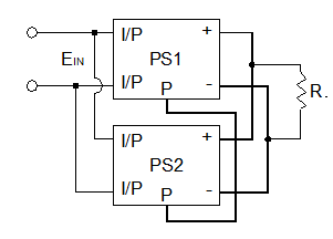
Figure 5.1: Wiring of S.P.S. with built-in parallel function
Notes on parallel operation:
1. Output voltage tolerance should be less than 0.2Vdc.
2. The power supplies should be paralleled using short and large diameter wiring and then connected to the load.
3. As power system is in full load condition, because of component tolerance, there is possibility that some of the power units being connected in parallel will reach to overcurrent limit therefore trigger over current protection and then overloads other units in the power system. Thus, we suggest the available output power to be de-rated to 90% of the total power.
Suggestions on Input and Output Wiring
(1) Input and output should be wired in opposite directions to prevent input surge and output ripple noise from interfering with each other.
(2) Output wiring should be short, thick, and meet the output current rating. Also, adding a small capacitor at the load can effectively reduce the noise.
(3) Suitable terminal screws, wires, and tools should be used when connecting to the terminal block.
(4) The FG (Frame Ground) of the AC input is different from the ground (-V / COM) of the DC output. There may be some isolation capacitors between them or it may be shorted together sometimes.
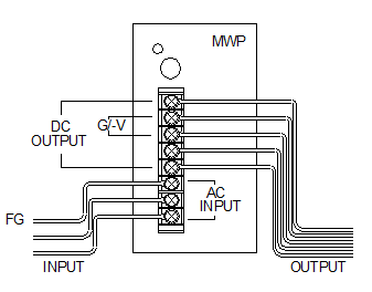
Figure 6.1 Wiring and connection
Leakage current considerations
Medical products have very stringent requirements for leakage currents, and MEAN WELL medical power supplies are designed to meet the safety requirement levels. However, the system level leakage current will increase when there are multiple power supplies in the system, thus when the end system needs to utilize multiple output voltages or power supplies, it is highly recommended to use medical grade modular power supplies, such as the NMP series, in order to ensure the leakage current requirements are met.
System requirements for applied parts (Type B, BF, or CF)
Power supplies are not medical equipment nor applied parts, and the power supplies shall not come in direct contact with the patients. Most medical equipment has medical grade power supplies, but only the parts of the equipment that comes into contact with the patients are classified as applied parts.
Applied parts for medical systems can be classified into Type B, BF, or CF:
| Type | Protection Level | Explanation | Equipment Example |
| Type B | Least strict | Does not come in contact with the patient during normal use and can be immediately removed if come in contact with the patient. | Respiratory equipment |
| Type BF | strict | Comes in contact with the patient during normal use, but does not touch the heart of the patient | ECG |
| Type CF | Most strict | Can come in contact with the patient heart during normal use | pacemaker |
Type B applied part can be grounded, but Type BF and CF applied parts must be “floating” and isolated from the ground. Depending on the applications and requirements of the end system, an appropriate power supplies and isolation shall be considered to ensure meeting the safety requirements for medical systems.
What is different between information (EN60950-1/IEC62368-1) and medical (EN60601-1) safety standard?
According to safety standard, the leakage current in EN60950-1 Class I cannot exceed 3.5mA; in EN60601-1 cannot exceed 0.3mA. Others criteria like safe distance and numbers of fuse are also different. Please consult the diagram below:

Can MEAN WELL's power supply be used in the range of 45Hz ~ 440Hz? If YES, what will happen?
MEAN WELL's power supply can be used within this frequency range. But if the frequency is too low, the efficiency will also be lower. For example, when a SP-200-24 is operated under 230VAC and rated load, if the frequency of AC input is 60 Hz, the efficiency is around 84%; however, if the frequency of AC input reduces to 50 Hz, the efficiency will be around 83.8%. If the frequency is too high, the power factor of the S.P.S. with PFC (power factor correction) function will reduce and this also will cause higher leakage current. For example, when a SP-200-24 is operated under 230VAC and rated load, if the frequency of AC input is 60 Hz, the power factor is 0.93 and the leakage current is around 0.7mA; however, if the frequency of AC input increase to 440 Hz, the power factor will decrease to 0.75 and the leakage current will rise to around 4.3mA.
A few things you should know before using the Remote Sensing function
First, use twisted wires, connect +S to the positive end of the output, then -S to the negative end of the output, as shown in the illustration. Also, keep the wires off the AC and output cables to prevent noise interference.
Add capacitors at output end where the Remote Sensing wires are connected to if dynamic load (frequency above 1K Hz) is used. The purpose is to reduce noise as Remote Sensing is a sensitive function. A suitable capacitor requires two factors:
a. Rated Ripple Current is 0.2 times greater than the output current
b. Rated Voltage is higher than the output voltage

What is the control mechanism for cooling fans?
Cooling fans have a relatively shorter lifetime (typical MTTF, Mean Time To Failure, of around 5000-100000 hours) compared with other components of power supply. As a result, changing operating method of the fans can extend the operation hours. The most common control schemes are shown as below:
- Temperature control: if the internal temperature of a power supply, detected by a temperature sensor, is over the threshold, the fan will start working at full speed, whereas, if the internal temperature is less than the set threshold, the fan will stop working or run at half speed. In addition, cooling fans in some power supplies are controlled by a non-linear control method whereby fan speed can be changed with different internal temperatures synchronously.
- Load control: if the loading of a power supply is over the threshold, the fan will start working at full speed, whereas, if the loading is less than the set threshold, the fan will stop working or run at half speed.
What is "Inrush Current"? What will we notice?
At input side, there will be (1/2 ~1 cycle, ex. 1/120 ~ 1/60 seconds for 60 Hz AC source) large pulse current (20~100A based on the design of S.P.S.) at the moment of power on and then back to normal rating. This "Inrush Current" will appear every time you turn on the power. Although it will not damage the power supply, we suggest not turning the power supply ON/OFF very quickly within a short time. Besides, if there are several power supplies turning on at the same time, the dispatching system of AC source may shut off and go into protection mode because of the huge inrush current. It is suggested that these power supplies start up one by one or use the remote control function of S.P.S. to turn them on/off.
What is PFC?
Power Factor Correction or PFC is to improve the ratio of apparent power to real power. The power factor is around 0.4~0.6 in non-PFC models. In models with PFC circuit, the power factor can reach above 0.95. The calculation formulas are as follows: Apparent Power=Input Voltage x Input Current (VA), Real Power= Input Voltage x Input Current x Power Factor (W).
From the point of view of environment friendly, the power plant needs to generate a power which is higher than apparent power in order to steadily provide electricity. The real usage of electricity is defined by real power. Assuming the power factor is 0.5, the power plant needs to produce more than 2WVA to satisfy 1W real power usage. On the contrary, if the power factor is 0.95, the power plant only needs to generate more than 1.06VA to provide 1W real power, It will be more effective in energy saving with PFC function.
Active PFC topologies can be divided into single-stage active PFC and two-stage active PFC, the difference is show as in the table below.
| PFC topology | Advantage | Disadvantage | Limitation |
| Single-stage active PFC |
Low cost Simple schematic High efficiency in small watt application |
Huge Ripple complex feedback control |
1.Zero “hold up time”. The output is affected by the AC input directly. 2.Huge ripple current results in lower LED life cycle.(drive the LED directly) 3.Low dynamic responds, easily affected by load. |
| Two-stage active PFC |
High efficiency Higher PF Easy feedback control High adoptive against load condition |
Higher cost Complex schematic |
Suitable for all kinds use |
What is power good and power fail signals and how can use it?
Some power supplies provide a "Power Good" signal when they are turned on, and send out a " Power Fail" signal when they are turned off. This is usually used for monitoring and controlling purpose.
Power Good: after the output of a power supply reaches 90% rated voltage, an TTL signal (about 5V) will be sent out within the next 10-500ms.
Power Fail: before the output of a power supply is less than 90% rated voltage, the power-good signal will be turned off at least 1ms in advance.

What are the protection forms of overload/overcurrent?
When current drawn exceeds the rating of the PSU, the protection circuit will be triggered to protect the unit against overload/overcurrent.
Protections of overload/overcurrent can be divided into several forms:
(1)FOLDBACK CURRENT LIMITING
Output current decreases about 20% of rated current, shown as curve (a) in the figure below.
(2)CONSTANT CURRENT LIMITING
Output current remains at a constant level and within the specified range while the output voltage drops to a lower level, shown as curve (b) in the figure below.
(3)OVER POWER LIMITING
Output power remains constant. As output load increases, output voltage decreases in proportion, shown as curve (c) in the figure below.
(4)HICCUP CURRENT LIMITING
Output voltage and current keep pulsing ON and OFF repeatedly when protection is activated. The unit automatically recovers when faulty condition is removed.
(5)SHUT OFF
Output voltage and current are cut off when output load reaches protection range.
NOTE: Protection mode of some of the products combines with different types of the forms mentioned, such as constant current limiting + shut down.
Recover method:
(1)Auto Recovery: PSU recovers automatically after faulty condition is removed.
(2)Re-power on: PSU restarts by manual AC re-power on after faulty condition is removed.
Note:Please do not operate PSU in overcurrent or short-circuit condition for a long period of time to prevent a shorten lifespan or damaging the PSU.