Programmable Power Supply Introduction
Tony Hsieh / Technical Service Engineer
MEAN WELL power supply featured with programmable voltage (PV) or programmable current (PC) function is generally realized by following two approaches:A. External analog voltage source
B. Digital (protocol) control interface
The output voltage/current of a switching power supply is changed via an external voltage source. This is so-called External analog voltage source. In general, the internal reference voltage of power supply for stabilizing a targeted output voltage is set at 2.5V. Another voltage level is taken and compared with the reference one. In case the voltage level is lower than 2.5V reference, the output of power supply will be higher than rated one and vice versa for making output voltage lower than rated one. Hence the programmable function is achieved by providing an external voltage source which will be level shifting inside a power supply and is compared with the reference. Figure 1 shows the block diagram of power supply with PV function via external voltage source.

Figure 1 Block diagram of power supply with PV function
The input range of PV function is basically allowing 1~5V due to the TTL logic level. The user can either use an external voltage source to provide or have a filter circuitry converting signal from PC into 1~5V level. Figure 2 shows the illustration for connecting PV connection.

Figure 2 PV function connection
The power supply with PV function is both designed and qualified only with DC level on PV control interface. It is not suggested having Pulse mode modulation (PWM) as input signal or use PV function to switch ON/OFF the power supply. If you have any specific needs, please contact MEAN WELL sales or engineering person for more details.
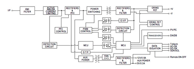
Digital control interface is achieved via the built-in microcontroller (MCU) which convert the instruction command of PMBus instruction into corresponding analog signal. The output of power supply is therefore determined by this analog signal. Compared with PV realized by external analog voltage approach, the digital control interface not only can have digital interface, but also provide the user much more functions including real-time and/or remote monitoring. Figure 3 shows the block diagram of power supply with Digital (protocol) control interface.

Figure 3 Block diagram of power supply with digital interface
Since the output of power supply can be easily changed or programmed based on the need of user, it can be used on a very wide range of applications. The followings are common applications:
• Burn-in equipment: the changeable voltage for various load/product
• Charging equipment: the customized charging curve
• LED lighting: PV to adjust the light intensity of strip
• Electroplating machine: PV to control the thickness of electroplating
• Electrolysis process: PV to control the chemical reaction
• Industrial printer: PV to determine the link level
